There are some electrical sensors mounted on the robot other than camera. The application of these sensors is shown below.
- 3 axis accelerometer(ADXL345, Analog Devices):Posture change detection, Getting off the track detection, Obstacle detection
- Hall effect sensor(A1324, Allegro MicroSystems):Touching ground detection, Obstacle detection
- Servo motor(KRS-3301,Kondo Kagaku):Posture change detection, Obstacle detection
For 3. servo motor, it may be not called as sensor. However it is comprised of motor and sensor so that I’ll add it to the list. As I posted earlier, accelerometer can be used to avoid obstacle and we can calculate velocity and displacement as well by taking cumulative sum of acceleration signal once and twice respectively. Accelerometer is cheap while it’s very useful. Here I’ll describe how to use accelerometer for posture change detection.
- We can detect posture change by taking inner product of current gravity acceleration and that of initial level and comparing with 1.0. Of course, we need to normalize two vectors as having length 1.0 before taking inner product. If current posture is close to initial level, inner product value is close to 1.0. If the robot is positioned at upside down, its value is close to -1.0.
- More gravity force is always applied to front side of the robot because the center of mass of scissors and arm is located away from that of robot platform. Therefore we need to correct posture in order to get closer to initial level of gravity acceleration vector as much as possible. When more gravity force is always applied to front side of the robot, it is applied to front legs most. Next is middle legs. And the force is applied to back legs least. Mechanical structure to measure pressure from the ground is comprised of hall effect sensor, diameter 3mm x hight 3mm cylinder Ferrite magnet, steel spring and support. Moreover, since the position of scissors and arm is off to the right, the force is applied to front-right leg most and it’s least at back-left leg diagonal to front-right leg.
- Simultaneously gap from desired angle of servo motor is largest at front legs. Next is middle legs. And gap is smallest at back legs. Moreover, since the position of scissors and arm is off to the right, gap is largest at front-right leg and it’s smallest at back-right leg diagonal to front-right leg.
- As I described, there is a relationship between signals from accelerometer, hall effect sensor and servo motor. So, we need to decide how to correct current posture using these 3 sensors comprehensively. It’s possible for us to deside whether posture change actually occurs or not accurately from multiple point of views.
- We can calculate desired servo angle by inverse kinematics so as to coincide foot tip with pre-defined touch point on the ground.
- I’ll implement the above procedure in the case robot doesn’t start walking. And then I’ll try to correct posture in real time.
Hello! Eventually we meet after one month passed… I thought about how to recognize weed in try&error manner. Anyway I’ll restart blog post.
Currently developed crab-like weed robot has a camera having 5mega pixel resolution. This camera is connected to Raspberry Pi Zero WH via CSI. At first I’ll describe overall process how to discriminate weed from captured image(Here I’ll not describe how to estimate distance from robot to weed).
- Select rectangular area dominant for green from captured image.
- Calculate super pixel in selected area and then select a segment dominant for green again. Other segments are set to black.
- Discriminate if selected segment contains leaf vein using cascade classifier.
For 1. we can discriminate in terms of RGB histogram (number of bin is 16)for rectangular area and relative peak for green is located at more right-hand side than blue and red. For 2. I used super pixel function implemented in OpenCV. And the process whether selected area is dominant for green or not is same as 1. For 3. I used cascade classifier deployed in OpenCV. Thanks for OpenCV developers!
How to select target area dominant for green
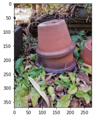
The following photo was taken at my native place via my smart phone. The size of original image is 1108 x 1478 pixel and resized it 1/4. Raspberry Pi Zero WH has only limited hardware resource and there are some additional tasks to be run in it so that I need to get small size images.
I split this image into 4 subareas(upper left,upper right,lower left, lower right)and select one area dominant for green. The selected area is shown below(eventually lower left area is selected).

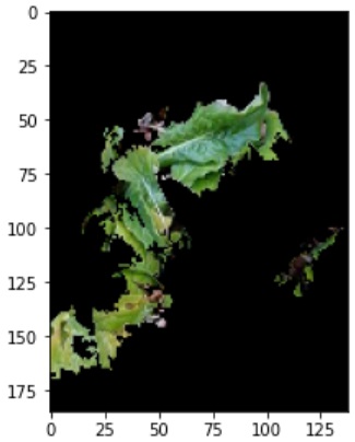
Super pixel calculation
The following image was extracted after super pixel is calculated and other segments not dominant for green are set to black. We can see black area in spite of weed leaf. This causes from severe criteria to discriminate whether target areas contain weed or not.
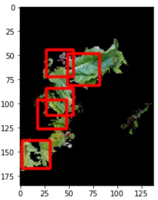
Cascade Classifier
Next we need to discriminate whether selected segment contains leaf vein or not using cascade classifier. I prepared for 700 sample images for both positive and negative. The following image is one of positive sample.

Next image shows selected segment with super imposed ROI (red rectangle) using learned classifier. For initial test, I could see many false-positive cases. However I got successful result after I used super pixel to focus on target segment dominant for green.
How do you feel about the above result? Anyway there were many try&errors to get final results. Next step is to describe how to detect weed in real time using a camera mounted on the robot.
When mounted camera recognizes weed by image processing, the following process will be run.
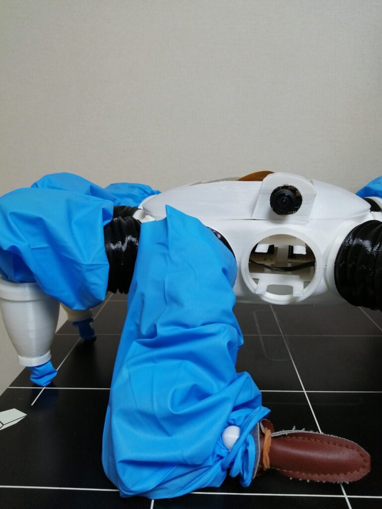
- Discriminate if weed is located at an area where arm can reach. We can decide it by that if weed is located in foreground and scissors is located in background. Scissors and arm are always located in front of the camera, we can see an 256×256 image including those objects if there is no occlusion. We can extract specific segment to scissors and arm from this image by calculating super pixel. Then we mask these segments and set other segments to black. We call it image ①. Although unfortunately there is a problem we couldn’t extract scissors as below photo shows, it can be resolved by seal it using same material (blue nitrile rubber) as arm is covered. Scissors and nitrile rubber will be glued using Cemedine 3000 series for hetero materials.

Next current captured image is called ②. Compare both image ① and ② while ROI is limited to scissors and arm segments included in image ① by that subtraction result of RGB color intensity of image ① from ② exceeds pre-defined threshold. Naturally even if weed is located closer to camera than scissors, there is a case it’s too close. However we can recogize this situation in terms of missing segment in blue cover when we calculate super pixel. Thus we can expect the subtraction result of RGB color intensity of image ① from ② exceeds pre-defined threshold.
- If weed is located in the area where arm can reach, we process an image in order to identify around the root of weed. We can use same image processing scheme as before, that is, already learned cascade classifier or subtraction of image sequence in a captured video. In the latter case, we try to identify when weed segment in an image is switched from background to foreground or weed is deformed. One of example is shown below. The process how to discriminate foreground and background is same as 1.

The advantage of foreground and background identification is that we can reuse same process as before. However this process can’t answer where should be cut. Although this is a subject to be considered later, we can recognize how scissors is far away from the ground in terms of current servo angle so that we will stop current motion immediately and switch the mode to exploration if the robot is about to cut extremely upper part of weed. - If weed is located in the area where arm can reach, we calculate servo angle in order to coincide the position of scissors rotate axis with root of weed by means of inverse kinematics. Scissors needs to be open by 30 degrees before required motion is realized. The process if scissors is located at appropriate position to cut around the root of weed is same as before. In this scenario one part of scissors is located at farthest, weed is middle and another part of scissors is closest. If scissors can’t reach appropriate position to cut around the root of weed, same process should be executed again after arm is returned to the original position. If scissors can’t catch weed three times, the robot gives up and then continue to explore other weeds after arm is returned to the original position.
- If scissors can catch weed successfully, main controller sends signal to servo motor to open/close scissors three times. Currently we don’t have a plan to see if scissors cuts weed successfully.
- If weed isn’t located in the area where arm can reach, the robot continues to search for another weed.
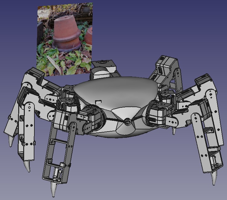
Next we describe the simulation procedure using 3D CAD.
- Create a new body on the ground and project an image containing weed on that body.
- Move the robot to forward direction.
- Discriminate if that image is located within the range of view field angle(horizontally160 degrees, vertically 90 degrees)。Here we simply think that image is located within the range if it is in front of camera.
- If image is located within the range, we decide the image contains weed or not.
- If image contains weed, we do image processing and arm control as described above section.
- Once it is successfully done, we increase number of sample images. Additional sample images should include negative case as well as positive one.
When we try to weed using autonomous robot, what to be considered is how to avoid obstacles. The strategy is categorized as following two groups.
- Obstacles are identified and avoided in advance by IR sensor、ultrasonic sensor、ToF sensor、camera(CMOS sensor)(Active obstacle avoidance)
- Once the robot hit obstacles then avoid it by accelerometer, pressure sensor, touch sensor.(Passive obstacle avoidance)
In the current case, robot has camera, hall effect sensor at foot and accelerometer.
In the current development phase, camera is only used to recognize target weed and isn’t used to avoid obstacles. This is because basic gait pattern of crab robot is side walk and the forward direction is normal to optical axis of camera. We can’t get appropriate information about image along with forward direction on time.
Currently used camera has 160 degrees field view. But it’s not sufficient to capture forward direction. If we want to capture forward direction, we need to select one of options, that is, to make camera rotationable, add a new camera and robot turns 90 degrees around at the current location. These approaches lead to complex mechanical structure or gait pattern.
Thus I chose passive obstacle avoidance approach. The process how to avoid obstacles is described in the following list.
- Signals (X,Y,Z) from accelerometer connected to Arduino Nano Every is gathered by constant time interval. In the current version, there is no gyro sensor on the robot because it has 6 legs so that rarely gets stucked with unstable posture. However there is a possibility foot tip gets stucked with pit fall and posture suddenly changes. In order to avoid this, we can utilize signal from hall effect sensor attached at foot tip. I’ll describe how to utilize it in another post.
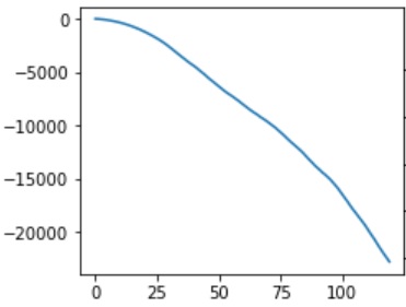
- It should be prepared for signal from accelerometer when there is no obstacle in advance according to gait pattern (forward, backward, turn left and turn right). The following chart represents displacement of X direction in the case of foward gait pattern. This chart shows monotonic decrease which means there is no obstacle. We can get dispacement information by taking cumulative sum of acceleration twice.
- Next chart represents displacement of X direction when there is a obstacle. We can easily see the gradient has been changed around at 75 steps.
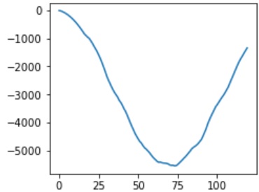
Compare two signals, that is, signal in the case there is no obstacle and that there is obstacle. Then if the difference between both of them exceeds pre-defined threshold, gait pattern should be changed from forward to backward and turn left/right. Rotational direction is decided randomly. For the value of threshold to trigger to change gait pattern, I’ll try to get signal from accelerometer some times and decide huristically. If threshold value is small, many events will occur when the robot hits obstacle and goes back and turn repeatedly. On the contrary, threshold value is large, the robot tries to go forward repeatedly even if it can’t go ahead. We need many trials to detect appropriate threshold value. The development of learning model is next target.
After the robot recognizes weed, we need to estimate distance to it. As I mentioned in another post, the robot has only single camera. If the robot has more one camera, we can estimate the distance to weed by disparity. But we need to search for another approach. The process how to estimate the distance to weed is shown below.
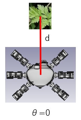
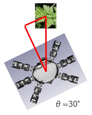
- Currently we can estimate the absolute distance to weed by rotating the robot along with vertical axis to the ground.
- When the robot recognizes weed, weed is located in front of the robot. After the robot rotates along with vertical axis to the ground, we can estimate the relative distance to weed by calculating the position in image.
- Here d is the distance to weed from robot and θ is rotational angle.
- When robot rotates θ, we measure the position of identical weed in before/after images and the distance from robot to weed. Then we derive the relationship among d,θ,P(x,y). Once we can get the relationship among d,θ,P(x,y), we can estimate the absolute distance from robot to weed.
- The key points for this process are how to derive the relationship among d,θ,P(x,y) and recognize identical weed in before and after images. In the latter case, we can compare both images by applying Gabor filter bank to calculate feature vectors and then select a window having minimum distance from before image to that of after.